Carefully read the questions and try to solve them intuitively.
Multiple questions can have the same circuit figure.
1 point
Find the time constant of the following circuit shown in figure 1.
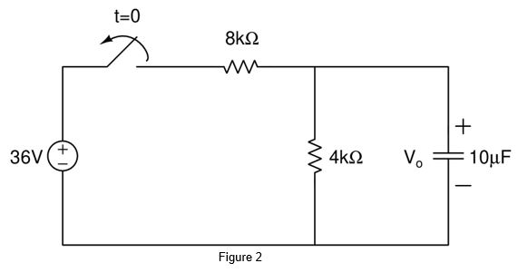
For the circuit shown in figure 2, the switch is opened at t = 0. Determine the time necessary for the capacitor voltage to decay to one-third of its value at t = 0. (Answer should be in milliseconds)
1 point
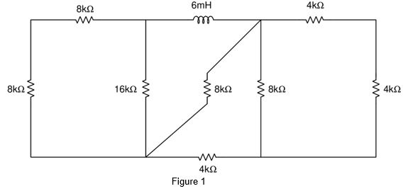
Find the time constant in the following circuit(Answer should be in seconds)
1 point
1 point
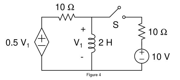
Find the time constant of the circuit shown in figure 4. (NOTE: The switch S closes at t = 0 sec)
1 point
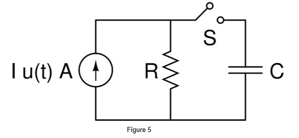
Consider the circuit given in figure 5 and find the following.
(NOTE: The switch S is closed at time t = 0 sec and the cap is initially uncharged)
i) ii)
1 point
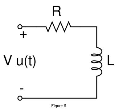
Find the time ‘t’ at which the voltage across both inductor and resistor is the same. Initially the inductor is relaxed. (T = Time constant)
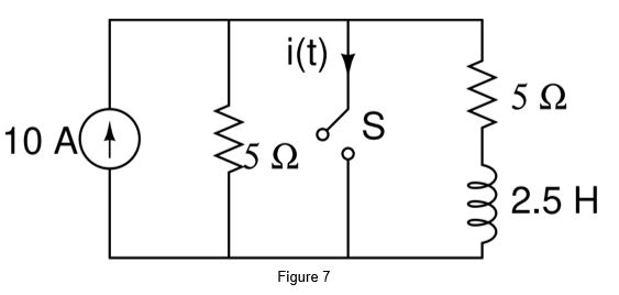
Find the current i(t) after t = 0.5 sec in figure 7. The current should be in Amps. (NOTE: The switch is closed at t = 0 sec. Initially the inductor is relaxed. The answer should be correct up-to 2 decimal places.)
1 point
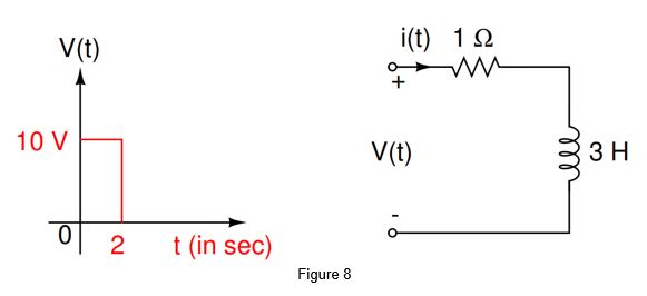
The value of i(t) at t = 2 sec in the circuit shown in figure 8 is _______ Amps in figure 8. (correct up-to two places of decimal)
1 point
1 point
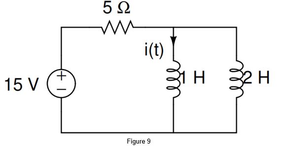
The steady state value of i(t) is
1 point
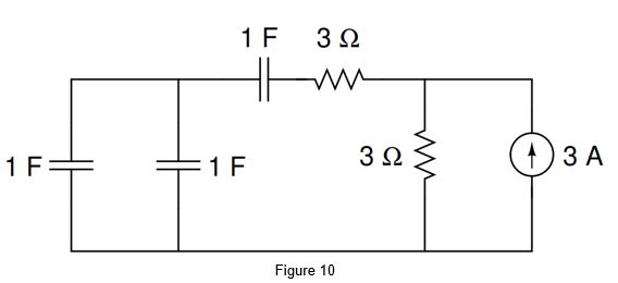
The time constant of the circuit given in figure 10 is
1 point
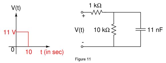
In the above circuit (Figure 11), the peak value of capacitor voltage is